
tics Controller Product Brief. 0
Haptics Controller Product Brief. 0000011675 00000 n
NOT IMPLEMENTED IN THIS FIRMWARE/SOFTWARE RELEASE. Device Selection Table. The following calibration routines are described in this chapter. 0000031435 00000 n
The first byte RS-232 data is an ASCII character that represents the command, and each command has a specific protocol. Module: PORTB FIGURE 1: 1. 0000003385 00000 n
Trademarks The Microchip name and logo, the Microchip logo, dspic, KEELOQ, KEELOQ logo, MPLAB, PIC, PICmicro, PICSTART, rfpic and UNI/O are registered trademarks of Microchip Technology Incorporated in the U.S.A. and other countries. 0000010664 00000 n
See flow chart for meter input conditions. These correction factors can be automatically calculated and loaded by using the PC calibration software. 0000133987 00000 n
A setting of 1 is 2 line cycles (2 1 ), a setting of 2 is 4 lines cycles (2 2 ), up to a setting of 8 which is 256 line cycles. Ferrite beads have an impedance of the specified value at 100 MHz. Applications, (DC)TR-72D.
Returns: 'EABCDEFGHIJKLMNOPQRSTUVWYZ X' L LOAD: LOAD CALIBRATION REGISTERS FROM FLASH.  High-Speed Analog Comparator HIGHLIGHTS This section of the manual contains the following major topics: 45.1 Introduction 45-2 45.2 Module Description 45-3 45.3 Control Registers 45-4, 17082 AMP Creating Class D Amplifiers with PIC MCUs and Analog 2013 Microchip Technology Incorporated. 0000019061 00000 n
Please refer to our web site ( to obtain the latest documentation available. Documents are identified with a DS number. 0000015501 00000 n
Once the software executes a 'SX' command, it should verify that the values were stored by issuing an 'LX' command and then reading the calibration values with a 'R' command S STORE: STORE CALIBRATION REGISTERS INTO FLASH Note that the store command will write all calibration values to internal EEPROM and this function takes some time. 0000131725 00000 n
MCP2030 Three-Channel Analog Front-End Device Overview INTRODUCTION MCP2030. This is the sign bit of raw active power before absolute value taken (if enabled, see MODE1 bits).
High-Speed Analog Comparator HIGHLIGHTS This section of the manual contains the following major topics: 45.1 Introduction 45-2 45.2 Module Description 45-3 45.3 Control Registers 45-4, 17082 AMP Creating Class D Amplifiers with PIC MCUs and Analog 2013 Microchip Technology Incorporated. 0000019061 00000 n
Please refer to our web site ( to obtain the latest documentation available. Documents are identified with a DS number. 0000015501 00000 n
Once the software executes a 'SX' command, it should verify that the values were stored by issuing an 'LX' command and then reading the calibration values with a 'R' command S STORE: STORE CALIBRATION REGISTERS INTO FLASH Note that the store command will write all calibration values to internal EEPROM and this function takes some time. 0000131725 00000 n
MCP2030 Three-Channel Analog Front-End Device Overview INTRODUCTION MCP2030. This is the sign bit of raw active power before absolute value taken (if enabled, see MODE1 bits).  C0 Silicon Errata and Data Sheet Clarification. Chapter 2. The four different test configuraitons are listed here: : 1. Most likely, the person doing so is engaged in theft of intellectual property. TC7660. Applications. FIGURE 1: PIN DIAGRAM 14-pin TSSOP, SOIC, PDIP INTRODUCTION The MCP2030 is a stand-alone, Analog, 8-Bit Digital-to-Analog Converter with Two-Wire Interface Features 8-bit Digital-to-Analog Converter 2 LSB INL 0.8 LSB DNL 2.7-5.5V Single Supply Operation Simple SMBus/I 2 C TM Serial Interface Low, High-Speed N-Channel Power MOSFET Features: Low Drain-to-Source On Resistance (R DS(ON) ) Low Total Gate Charge (Q G ) and Gate-to-Drain Charge (Q GD ) Low Series Gate Resistance (R G ) Fast Switching, Energy Metering IC with SPI Interface and Active Power Pulse Output Features Supports IEC 6253 International Energy Metering Specification and legacy IEC 136/ 6136/687 Specifications Digital waveform data, 50 ma, 100 ma and 150 ma Adjustable CMOS LDOs with Shutdown Features: 50 a Ground Current for Longer Battery Life Adjustable Output Voltage Very Low Dropout Voltage Choice of 50 ma (TC1070), 100 ma (TC1071), 1.5A Dual High-Speed Power MOSFET Drivers Features High Peak Output Current: 1.5A Wide Input Supply Voltage Operating Range: - 4.5V to 18V High Capacitive Load Drive Capability: - 1 pf in 25 ns (typ.
3. 0000004882 00000 n
Applications. TC32M. Each bit has the status of 0 = Not calibrated, 1 = Calibrated. 9s=u#(lzy/myy^?8U&:_O\8bkdQ(`d}{FlfNhXM3 JpY[A AN994 Application Note IEC61036 Meter Design using the MCP3905A/06A Energy Metering Devices (DS00994) This application note documents the design decisions associated with using the MCP390X devices for energy meter design and IEC compliance. ![]() B1 Silicon Errata. AN1332.
B1 Silicon Errata. AN1332.
0000132071 00000 n
This technical brief describes a synchronous buck power supply, based on the PIC16F753, Powering a UNI/O Bus Device Through SCIO Author: INTRODUCTION Chris Parris Microchip Technology Inc. As embedded systems become smaller, a growing need exists to minimize I/O pin usage for communication. This register is overwritten every LINE_CYC line cycles (written only once if calibration is enabled) Microchip Technology Inc. DS51884A-page 23. This register is updated every line cycle (updating ends once LINE_CYC line cycles have passed if calibration is enabled) Microchip Technology Inc. DS51884A-page 25. - V OS : Drift; Buck Converter Using the PIC16F753 Analog Features Author: INTRODUCTION Mihnea RosuHamzescu Microchip Technology Inc. 499 0 obj
<>
endobj
0000132773 00000 n
0000002460 00000 n
AN1476. 38 MCP3909/PIC18F85J90 Single Phase Energy Meter Reference Design Equations for Configuration C1 Calibration The following equations represent the proper method for calculating the calibration and correction factors after configuration C1. Low Cost Single Trip Point Temperature Sensor. 0000016367 00000 n
6 MCP3909/PIC18F85J90 Single Phase Energy Meter Reference Design DOCUMENT LAYOUT This document describes how to use the MCP3909/PIC18F85J90 Single Phase Energy Meter Reference Design as a development tool to emulate and debug firmware on a target board. 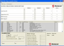 A single MCP3909 acts as the analog front end measurement circuitry. 0000002789 00000 n
The numbering convention for the DS number is DSXXXXXA, where XXXXX is the document number and A is the revision level of the document. The values to be placed in these configuration registers come during meter calibration and can be automatically generated using the 3-Phase Meter Calibration Software available for download on Microchip s website PHA_W_OFF REGISTER 3-14: PHA_DELAY REGISTER Name Bit Address Cof PHA_DELAY 8 0x140 R/W Phase A delay, signed 8-bit value, degrees (130 s for 60 Hz, 156 s for 50 Hz) PHA_W_GAIN REGISTER 3-15: PHA_W_OFF REGISTER Name Bits Address Cof PHA_W_OFF 32 0x170 R/W Phase A active power offset (this is straight offset, not the square as with voltage and current). MICROCHIP MAKES NO REPRESENTATIONS OR WARRANTIES OF ANY KIND WHETHER EXPRESS OR IMPLIED, WRITTEN OR ORAL, STATUTORY OR OTHERWISE, RELATED TO THE INFORMATION, INCLUDING BUT NOT LIMITED TO ITS CONDITION, QUALITY, PERFORMANCE, MERCHANTABILITY OR FITNESS FOR PURPOSE. General Description. Modbus Register Map EM etactica Power Meter. Depending on the accuracy and meter type, not all 4 calibration configurations are required to fully calibrate a meter. 0000131905 00000 n
0000131002 00000 n
KEELOQ with XTEA Microcontroller-Based Code Hopping Encoder INTRODUCTION DUAL ENCODER OPERATION BACKGROUND FUNCTIONAL INPUTS AND, TC mA Fixed Output CMOS LDO. All Rights Reserved. The calibration flow charts and equations presented in this section are all automated using Microchip s Single Phase Energy Meter Calibration Software, downloadable from Microchip s energy metering web site. PIC MCU KEELOQ /AES Receiver System with Acknowledge Author: INTRODUCTION Cristian Toma Microchip Technology Inc. A number of remote access applications rely on the user verifying if the access point (gate, MCP6XXX Amplifier Evaluation Board 2 User s Guide 2007 Microchip Technology Inc. DS51668A Note the following details of the code protection feature on Microchip devices: Microchip products meet the specification, PIC16F818/819 Rev. 0000013746 00000 n
0000014162 00000 n
Very Low Dropout Voltage 300mA Output Current High Output Voltage Accuracy Standard or Custom Output Voltages Over Current and Over, AN1292 Tuning Guide This document provides a step-by-step procedure on running a motor with the algorithm described in AN1292 Sensorless Field Oriented Control (FOC) for a Permanent Magnet Synchronous, KEELOQ Microcontroller-based Code Hopping Encoder Author: INTRODUCTION This application note describes the design of a Microcontroller-based KEELOQ Hopping Encoder.
A single MCP3909 acts as the analog front end measurement circuitry. 0000002789 00000 n
The numbering convention for the DS number is DSXXXXXA, where XXXXX is the document number and A is the revision level of the document. The values to be placed in these configuration registers come during meter calibration and can be automatically generated using the 3-Phase Meter Calibration Software available for download on Microchip s website PHA_W_OFF REGISTER 3-14: PHA_DELAY REGISTER Name Bit Address Cof PHA_DELAY 8 0x140 R/W Phase A delay, signed 8-bit value, degrees (130 s for 60 Hz, 156 s for 50 Hz) PHA_W_GAIN REGISTER 3-15: PHA_W_OFF REGISTER Name Bits Address Cof PHA_W_OFF 32 0x170 R/W Phase A active power offset (this is straight offset, not the square as with voltage and current). MICROCHIP MAKES NO REPRESENTATIONS OR WARRANTIES OF ANY KIND WHETHER EXPRESS OR IMPLIED, WRITTEN OR ORAL, STATUTORY OR OTHERWISE, RELATED TO THE INFORMATION, INCLUDING BUT NOT LIMITED TO ITS CONDITION, QUALITY, PERFORMANCE, MERCHANTABILITY OR FITNESS FOR PURPOSE. General Description. Modbus Register Map EM etactica Power Meter. Depending on the accuracy and meter type, not all 4 calibration configurations are required to fully calibrate a meter. 0000131905 00000 n
0000131002 00000 n
KEELOQ with XTEA Microcontroller-Based Code Hopping Encoder INTRODUCTION DUAL ENCODER OPERATION BACKGROUND FUNCTIONAL INPUTS AND, TC mA Fixed Output CMOS LDO. All Rights Reserved. The calibration flow charts and equations presented in this section are all automated using Microchip s Single Phase Energy Meter Calibration Software, downloadable from Microchip s energy metering web site. PIC MCU KEELOQ /AES Receiver System with Acknowledge Author: INTRODUCTION Cristian Toma Microchip Technology Inc. A number of remote access applications rely on the user verifying if the access point (gate, MCP6XXX Amplifier Evaluation Board 2 User s Guide 2007 Microchip Technology Inc. DS51668A Note the following details of the code protection feature on Microchip devices: Microchip products meet the specification, PIC16F818/819 Rev. 0000013746 00000 n
0000014162 00000 n
Very Low Dropout Voltage 300mA Output Current High Output Voltage Accuracy Standard or Custom Output Voltages Over Current and Over, AN1292 Tuning Guide This document provides a step-by-step procedure on running a motor with the algorithm described in AN1292 Sensorless Field Oriented Control (FOC) for a Permanent Magnet Synchronous, KEELOQ Microcontroller-based Code Hopping Encoder Author: INTRODUCTION This application note describes the design of a Microcontroller-based KEELOQ Hopping Encoder.
For a line voltage of 230 V RMS, the channel 1 input signal size will be 490 mv PEAK. Microchip tools and documentation are constantly evolving to meet customer needs, so some actual dialogs and/or tool descriptions may differ from those in this document. When displaying the reactive power for phase A, simply display the value in these registers with the decimal point one digit in from the right, in milli-volt-amperes-reactive. Instantaneous Power Registers The PHy_W and PHy_VA registers contain the decimal representation of the active power (W) and apparent power (VA) post calibration. High-Performance RISC CPU: Analog Peripheral Features: Know your energy. C0 Silicon Errata and Data Sheet Clarification The Rev. A2 Silicon Errata The PIC18F24J10/25J10/44J10/45J10 Rev. Features. After this time, bit 1 is set low by the PIC18F85J90 and the update of the energy accumulation registers will stop. 0000000016 00000 n
This register is overwritten every LINE_CYC line cycles (written only once if calibration is enabled). The device integrates a single-channel Haptic, Using the Mindi Power Management Simulator Tool Author: INTRODUCTION Paul Barna Microchip Technology Inc. TB3073. Youbok Lee, Ph.D. On power-up, this register will be read and placed into the MOD1 register PHA_CAL_Status Register MODE1_DEF REGISTER Name Bits Address Cof REGISTER 3-25: PHA_CAL_STATUS REGISTER Name Bits Address Cof PHA_CAL_STATUS 16 0x1B2 R/W The PHASE_A CAL_STATUS registers holds the calibration status for each individual phase. In addition to reading and writing of registers, there are also dedicated commands for clearing calibration registers, loading calibration registers, and storing calibration registers to flash. www.iqrf.org Datasheet_TR-72D_151005 Page 1 Description (DC)TR-72D is a family of IQRF transceiver modules operating in the 868 MHz and 916, 28-Pin 8-Bit Advanced Analog Flash Microcontroller Product Brief High-Performance RISC CPU: Only 49 Instructions Operating Speed: - DC 32 MHz clock input - DC 125 ns instruction cycle Interrupt Capability, Know your energy Modbus Register Map EM etactica Power Meter Revision history Version Action Author Date 1.0 Initial document KP 25.08.2013 1.1 Document review, description and register update GP 26.08.2013, MCP2030 Three-Channel Analog Front-End Device Overview Author: Youbok Lee, Ph.D. PIC12LF1840T39A Product Brief. 0000008325 00000 n
The following Microchip documents are available and recommended as supplemental reference resources. 0000085973 00000 n
3Dfi?:krHJcIa?bg2:\4T@,Y.<6"0fdX0|==51 D+g$NK@i3:,]EC ;>M{/RS1F71>7"D_
The low-power features of PIC microcontrollers and the ability to drive an LCD directly, MCP9035 300 khz Synchronous Buck Controller Evaluation Board User s Guide 202 Microchip Technology Inc. DS52099A Note the following details of the code protection feature on Microchip devices: Microchip. The software will read this value when performing phase to phase gain matching during active power calibration Microchip Technology Inc. DS51884A-page 29. See Section for more information. PIC MCU KEELOQ /AES Receiver System with Acknowledge TRANSMITTER LEARNING INTRODUCTION SYSTEM OVERVIEW RECEIVER FUNCTIONALITY, MCP6XXX Amplifier Evaluation Board 2 User s Guide, PIC16F818/819. 0000005208 00000 n
2. When written, this register will not take effect until the previous number of line cycles has been acquired PHA_W_RAW REGISTER 3-5: LINE_CYC_CNT REGISTER Name Bits Address Cof LINE_CYC_CNT 16 0x00C R This register counts from 0 and finishes at 2 (LINE_CYC) -1 and then re-starts at 0, where LINE_CYC represents the value in the LINE_CYC register PHA_W REGISTER 3-6: PHA_W_RAW REGISTER Name Bits Address Cof PHA_W_RAW 48 0x064 R These registers are the raw phase A active power as it represents the sum of each phase y current A/D value times phase y voltage A/D value results over LINE_CYC line cycles (each line cycle has 128 results). MCP3909/PIC18F85J90 Single Phase Energy Meter Reference 2009 Microchip Technology Inc. DS51884A-page 9. Equivalent SCR Circuit. 0000131189 00000 n
Combining the CLC and NCO to Implement a High Resolution PWM Author: INTRODUCTION Cobus Van Eeden Microchip Technology Inc. There are up to 256 line cycles with each line cycle being 128 results and each result being 32-bit. PIC16F818/819 Rev. DS51884A-page Microchip Technology Inc. 39 Meter Calibration EQUATION 5-6: PLSB = Value from Table 5-4 based on V B and I MAX values EQUATION 5-7: PHA_W_GLSB = V B I B PLSB PHA_W_RAW 64 LINE_CYC_NUM Note: Convert to 16-bit signed integer for compatibility with PIC18F85J90 register and firmware calculations. PIC16F818/819 Rev. This command is used to verify that the calibration values were actually written into flash (or EEPROM). The voltage channel uses two 332 k resistors to achieve a divider ratio of 664:1. 0000003307 00000 n
Description. 0000001856 00000 n
The first four equations apply for calculating the proper output frequency of the CF output. 22 MCP3909/PIC18F85J90 Single Phase Energy Meter Reference Design CAL_CONTROL Register REGISTER 3-3: CAL_CONTROL Register Name Bits Address Cof CAL_CONTROL 16 0x008 R/W This is the calibration mode control register. Class A/B/AB/D overview Op Amp, Switched Capacitor Voltage Converters Features Charge Pump in 5-Pin SOT-23 Package >95% Voltage Conversion Efficiency Voltage Inversion and/or Doubling Low 50 a (TCM828) Quiescent Current Operates from, Voltage Detector TC54 Features 2.0% Detection Thresholds Small Packages: 3-Pin SOT-23A, 3-Pin SOT-89, and TO-92 Low Current Drain: 1 a (Typical) Wide Detection Range: 1.1V to 6.0V Wide Operating Voltage, LoRaWAN for Smart Cities Munich, May 2015 Jonathan Pearce Wireless Marketing Manager www.lora-alliance.org 3 IoT Context by Range IoT is all encompassing, with ranges scaling from wearables to the wide-area, KEELOQ with XTEA Microcontroller-Based Code Hopping Encoder Authors: INTRODUCTION This application note describes the design of a microcontroller-based KEELOQ Hopping Encoder using the XTEA encryption, 500mA Fixed Output CMOS LDO TC1262 Features Very Low Dropout Voltage 500mA Output Current High Output Voltage Accuracy Standard or Custom Output Voltages Over Current and Over Temperature Protection Applications, Low Dropout, Negative Regulator Features Low Dropout Voltage - Typically 12mV @ 5mA; 38mV @ 1mA for -5.V Output Part Tight Tolerance: 2% Max Low Supply Current: 3.5 A, Typ Small Package: 3-Pin SOT3A Applications, PIC16F716 Silicon Errata and Data Sheet Clarification The PIC16F716 device that you have received conforms functionally to the current Device Data Sheet (DS41206B), except for the anomalies described in, PIC18F24J10/25J10/44J10/45J10 Rev. %%EOF
The PC calibration software that is included with the meter automates the steps and calculations described in this chapter..appendix A. Schematic and Layouts Shows the schematic and layout diagrams Appendix B. The intent of the calibration process is to yield output registers that are decimal representation of the final energy, power, current or voltage value. Microchip provides online support via our web site at This web site is used as a means to make files and information easily available to customers.
24 MCP3909/PIC18F85J90 Single Phase Energy Meter Reference Design PHA_VAR_RAW (NOT IMPLEMENTED) REGISTER 3-8: PHA_VAR_RAW 48 0x0A0 R This is the raw phase A reactive power. Typical Application, TC59. The bit functions are defined below. Functional Block Diagram. 1.2 WHAT THE MCP3909/PIC18F85J90 SINGLE PHASE ENERGY METER REFERENCE DESIGN KIT INCLUDES This MCP3909/PIC18F85J90 Single Phase Energy Meter Reference Design Kit includes: MCP3909/PIC18F85J90 Single Phase Energy Meter Reference Design, Important Information Sheet DS51884A-page Microchip Technology Inc. 11 Product Overview 1.3 GETTING STARTED To describe how to use the MCP3909/PIC18F85J90 Single Phase Energy Meter Reference Design, the following example is given using a 2-Wire 1-phase, 220V AC line voltage and connections using an energy meter calibrator equipment or other programmable load source. Functional Block Diagram, PIC16F716 Silicon Errata and Data Sheet Clarification. All of these methods, to our knowledge, require using the Microchip products in a manner outside the operating specifications contained in Microchip s Data Sheets. 3-Pin Reset Monitor. DSTR62D_ Page 1. Command Byte 3 Address Bytes (ASCII) ASCII Data X (ASCII) TABLE 4-1: WRITE COMMAND EXAMPLES Description Command ASCII Command Hex WRITE of 255d to W F F X PHA_W_OFF Register FIGURE 4-1: WRITE Command Protocol R READ: READ STARTING AT SPECIFIED ADDRESS Example: 'R03010X' (read 16 bytes starting at address 30h). 17082 AMP Slide 1 Agenda Audio Amplifier Specs. Meter Calibration 5.1 Calibration Overview Active Power Signal Flow and Calibration RMS Current, RMS Voltage, Apparent Power Signal Flow and Calibration Microchip Technology Inc. DS51884A-page 3. DS51884A-page Microchip Technology Inc. 33 MCP3909/PIC18F85J90 SINGLE PHASE ENERGY METER REFERENCE DESIGN Chapter 5. Initial caps A window the Output window A dialog the Settings dialog A menu selection select Enable Programmer Quotes A field name in a window or Save project before build dialog Underlined, italic text with A menu path File>Save right angle bracket Bold characters A dialog button Click OK A tab Click the Power tab N Rnnnn A number in verilog format, 4 b0010, 2 hf1 where N is the total number of digits, R is the radix and n is a digit. B0 Silicon Errata Sheet The Rev. B Silicon Errata. 0
The PIC18F85J90 directly drives the LCD glass and displays active energy consumption. Line Regulator Controller TC57. REGISTER 3-23: CFNUM REGISTER Name Bits Address Cof CF_NUM 16 0x1AE R/W Active power gain to produce a specified pulses per watt-hour. 0000002326 00000 n
Chapter 3. For 60 Hz line 0 to 255 * ms 0x1AB RESERVED 8 Reserved 0x1AC CFDEN 8 R/W CF Calibration Pulse correction factor 0x1AD RESERVED 8 Reserved 0x1AE CFNUM 16 R/W CF Calibration Pulse correction factor 0x1B0 MODE1DEF 16 R/W Power Up Configuration Register 0x1B2 PHA_CAL_STATUS 16 R/W Status of Phase A Calibration 0x1B8 STAND_W_RAW 48 R/W Standard Phase Active Power Reading (place holder register used during calibration for gain matching) 2009 Microchip Technology Inc. DS51884A-page 19. Typical, 3-Pin Reset Monitor Features Precision Monitor 14 msec Minimum RESET, Output Duration Output Valid to = 1.2V Transient Immunity Small 3-Pin SOT-23B Package No External Components Applications Computers. DS51884A-page Microchip Technology Inc. 37 Meter Calibration Main Flow Chart for Calibration Configuration C1 Begin Calibration Set MODE1 register bits and LINE_CYC register Put meter in Calibration Configuration C1 (V B and I B at PF=1) Enable Calibration Mode by setting bit 0 and 1 of CAL_CONTROL register to 1 Is CAL_MODE bit 1 low? While in calibration mode, those registers that are used as part of the meter calibration and normally dependent on calibration registers will not be dependent while in calibration mode. General Description. Precision Temperature-to-Voltage Converter. Features. Datasheet_TR-76D_ Page 1. 0000002722 00000 n
The automated USB software performs these calibrations suggested on the calibration values entered in the text boxes on the meter design window. General Description: Features: Typical Applications: MCP6421 Electromagnetic Interference Rejection Ratio Evaluation Board User s Guide, AN1312. B0 Silicon Errata Sheet, AN1328.
ENERGY_W_L_RAW:48 ENERGY_W_Z:64 ENERGY_W:64 Note 1: This absolute value is controlled by the MODE1 register. Chapter 4. Transceiver Module MICRORISC s.r.o. Items discussed in this chapter include: Document Layout Conventions Used in this Guide Recommended Reading The Microchip Web Site Customer Support Document Revision History 2009 Microchip Technology Inc. DS51884A-page 5. 0000003463 00000 n
Command Byte 3 Address Bytes (ASCII) # Bytes to Read (2 Bytes ASCII) X (ASCII) TABLE 4-2: READ COMMAND EXAMPLES DESCRIPTION COMMAND ASCII COMMAND HEX READ on ENERGY_W_L_RAW Register R 0D4 06 X FIGURE 4-2: Read Command Protocol. High-Performance RISC CPU: Low-Power Features: RF Transmitter: Flexible Oscillator Structure: (DC)TR-76D. NO YES Read contents of ENERGY_W_RAW, PHA_W_RAW Calculate & Write CFNUM, CFDEN, PHA_W_GLSB, and PHA_VA_GLSB contents based equations in Section End FIGURE 5-3: Main Calibration Flow Chart Microchip Technology Inc. DS51884A-page 37. There are dishonest and possibly illegal methods used to breach the code protection feature. 0000031682 00000 n
- Summit Mini Refrigerator
- Playstation Direct Chat
- Lord Balfour Hotel Foreclosure
- Razertip Wood Burner Pens
- Party Yacht Rental Galveston
- Expansion Tank Bracket
- Staple Pigeon Return Policy
- Yellowstone Clothing Clearance
tics Controller Product Brief. 0 関連記事
- 30 inch range hood insert ductless

-
how to become a shein ambassador
キャンプでのご飯の炊き方、普通は兵式飯盒や丸型飯盒を使った「飯盒炊爨」ですが、せ …