
eatedly drive and remove a nail
Repeatedly drive and remove a nail into the wall in the area of the stud until it is located. Check for doorway and high movement areas. Description 1 2 3 4 5 6 7 8 9 10 11 Register Assembly Strain Relief Bushing J-Box Cover Strain Relief Bushing Heat Sensor Switch Fan Switch Motor and Blower Motor cover Motor Housing Back Plate Cord and Plug Bushing Use only manufacturers authorized parts. POSSIBLE CAUSE(S) a. CORRECTIVE ACTION a. b. Compact Heating System Product Brochure, Williams Furnace Co. Vent-Free Fireboxes & Fireplace Logs Product Brochure, Williams Furnace Co. Monterey Home Furnaces Product Brochure, Williams Furnace Co. Forsaire Counterflow Furnaces Product Brochure, Williams Furnace Co. Vented Fireplace Logs Product Brochure. Inner coneblue in color3/8 to 5/8-inches above ports. Hints and Information Service Hints If your furnace fails to work correctly, you may avoid the inconvenience and cost of a service call by checking the troubleshooting section on pages 38 and 39 before you call for service. Do not cut or remove the prong. It is necessary to clean this area regularly. 76 0 obj
<<
/Linearized 1
/O 78
/H [ 1043 418 ]
/L 923067
/E 35768
/N 20
/T 921429
>>
endobj
xref
76 32
0000000016 00000 n
0000000988 00000 n
0000001461 00000 n
0000001669 00000 n
0000001890 00000 n
0000002070 00000 n
0000002176 00000 n
0000002283 00000 n
0000002305 00000 n
0000006813 00000 n
0000006835 00000 n
0000011275 00000 n
0000011344 00000 n
0000011366 00000 n
0000015496 00000 n
0000015518 00000 n
0000018895 00000 n
0000018917 00000 n
0000021895 00000 n
0000021917 00000 n
0000025368 00000 n
0000025422 00000 n
0000025444 00000 n
0000028812 00000 n
0000028834 00000 n
0000032104 00000 n
0000032182 00000 n
0000032261 00000 n
0000033171 00000 n
0000034098 00000 n
0000001043 00000 n
0000001439 00000 n
trailer
<<
/Size 108
/Info 75 0 R
/Root 77 0 R
/Prev 921419
/ID[<0737c2fa36dc608fad701b4994ff3f00><0737c2fa36dc608fad701b4994ff3f00>]
>>
startxref
0
%%EOF
77 0 obj
<<
/Type /Catalog
/Pages 73 0 R
>>
endobj
106 0 obj
<< /S 327 /Filter /FlateDecode /Length 107 0 R >>
stream
+q;|?B2':L:?2++=LG[qvq=zS
.gWzNC y.y._W\k979o\wx$2:EJQ@FvyYVF,? 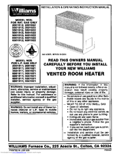 /Subtype /Image
/ColorSpace /DeviceGray
flammable vapors and liquids in the vicinity, Do not touch any electrical switch; do not, Installation and service must be performed, Heating, Ventilation, and Air Conditioning, 35,000 BTU/Hr Monterey Top-Vent Gravity Wall Furnace Natural Gas with Wall or Cabinet-Mounted Thermostat. Current to the thermostat is supplied by the pilot generator. b Copyright 2020 Inmar-OIQ, LLC All Rights Reserved. Straighten or replace. /Length 6 0 R
Remove control access panel. Installing Your Furnace Locating Wall Furnace & Thermostat (continued) The thermostat should be sensing average room temperature; avoid the following: HOT SPOTS: Concealed pipes or ducts Fireplaces Registers TV sets Radios Lamps Direct sunlight Kitchen COLD SPOTS: Concealed pipes or ducts Stairwells drafts Doors drafts Unheated rooms on other side of wall After picking a location that meets the requirements, check the walls, attic and roof to make sure there are no obstructions such as pipes, electric. DO NOT store or use gasoline or other flammable vapors and liquids in the vicinity or this or any other appliance. Installing Your Furnace Recessed Wall Mount Installation On models 2509621A, 2519621A, 2539621A, 2559621A, 2509622A, 2519622A, 2539622A, 2559622A, 3509621A, 3519621A, 3539621A, 3559621A, 3509622A, 3519622A, 3539622A, and 3559622A, the maximum recess depth from rear of furnace forward is 4-inches. a. b. c. Housing rattling. 2. 7. Installing Your Motorized Rear Outlet Accessory Motorized Rear Outlet Register 6919 and 6920 WARNING: Danger of property damage, bodily injury or death. Install the furnace in accordance with local codes or ordinances and instructions provided. Williams Furnace Co., 250 West Laurel Street, Colton, CA 92324 U.S.A. (SEE WARNING). Check connections at valve terminals. Use the free area of a louver or grille to determine the size opening required to provide the free area specified. If in doubt, consult your local codes or inspector. %PDF-1.2
information, consult a qualified installer, furnace should be inspected before use and at, product could expose you to substances in, fuel or from fuel combustion which can cause, death or serious illness and which are known. If flame needs adjusting, do so as follows: ANNUAL UPKEEP NEEDED 1. Use the 18-gauge wire as supplied for a maximum length of 20-feet. Installing Your Furnace Attaching Your Furnace Clear the wall recess of all debris, remove any wood or plaster. If you have any doubts as to any requirements, check with local authorities. Never attempt start-up of unit before thoroughly ventilating the area. Furnace Replacement Parts Furnace Replacement Parts (continued) Control Assembly 250, 350 & 500 Series REF.
/Subtype /Image
/ColorSpace /DeviceGray
flammable vapors and liquids in the vicinity, Do not touch any electrical switch; do not, Installation and service must be performed, Heating, Ventilation, and Air Conditioning, 35,000 BTU/Hr Monterey Top-Vent Gravity Wall Furnace Natural Gas with Wall or Cabinet-Mounted Thermostat. Current to the thermostat is supplied by the pilot generator. b Copyright 2020 Inmar-OIQ, LLC All Rights Reserved. Straighten or replace. /Length 6 0 R
Remove control access panel. Installing Your Furnace Locating Wall Furnace & Thermostat (continued) The thermostat should be sensing average room temperature; avoid the following: HOT SPOTS: Concealed pipes or ducts Fireplaces Registers TV sets Radios Lamps Direct sunlight Kitchen COLD SPOTS: Concealed pipes or ducts Stairwells drafts Doors drafts Unheated rooms on other side of wall After picking a location that meets the requirements, check the walls, attic and roof to make sure there are no obstructions such as pipes, electric. DO NOT store or use gasoline or other flammable vapors and liquids in the vicinity or this or any other appliance. Installing Your Furnace Recessed Wall Mount Installation On models 2509621A, 2519621A, 2539621A, 2559621A, 2509622A, 2519622A, 2539622A, 2559622A, 3509621A, 3519621A, 3539621A, 3559621A, 3509622A, 3519622A, 3539622A, and 3559622A, the maximum recess depth from rear of furnace forward is 4-inches. a. b. c. Housing rattling. 2. 7. Installing Your Motorized Rear Outlet Accessory Motorized Rear Outlet Register 6919 and 6920 WARNING: Danger of property damage, bodily injury or death. Install the furnace in accordance with local codes or ordinances and instructions provided. Williams Furnace Co., 250 West Laurel Street, Colton, CA 92324 U.S.A. (SEE WARNING). Check connections at valve terminals. Use the free area of a louver or grille to determine the size opening required to provide the free area specified. If in doubt, consult your local codes or inspector. %PDF-1.2
information, consult a qualified installer, furnace should be inspected before use and at, product could expose you to substances in, fuel or from fuel combustion which can cause, death or serious illness and which are known. If flame needs adjusting, do so as follows: ANNUAL UPKEEP NEEDED 1. Use the 18-gauge wire as supplied for a maximum length of 20-feet. Installing Your Furnace Attaching Your Furnace Clear the wall recess of all debris, remove any wood or plaster. If you have any doubts as to any requirements, check with local authorities. Never attempt start-up of unit before thoroughly ventilating the area. Furnace Replacement Parts Furnace Replacement Parts (continued) Control Assembly 250, 350 & 500 Series REF.
f. g. Gas valve not turned to the ON position after lighting pilot. e. Defective gas valve. Immediately call a qualified service technician to inspect the appliance and to replace any part of the control system and any gas control which has been under water. Troubleshooting Your Furnace SYMPTOM 1. I have a Williams 625 DVX-R LPGeach time i turn williams direct vent wall furnace model #4007732 If any sparking, odors or unusual noises are encountered, shut off electric power immediately. Swing bottom of furnace into wall recess with front edges of legs flush with 2x4 floor plate. No. Replace control access panel. Installing Your Furnace Surface Mount Installation The use of the optional Free Standing Accessory No. Top-Vent Gravity Wall Furnace Model Numbers: 2509622A; 2519622A; 2539622A; 2559622A; 3509622A; 3519622A: 3539622A; 3559622A; 5009622A; 5019622A; 5039622A; 5059622A FOR USE WITH NATURAL GAS ONLY Model Numbers: 2509621A; 2519621A; 2539621A; 2559621A; 3509621A; 3519621A; 3539621A; 3559621A; 5009621A; 5019621A; 5039621A; 5059621A FOR USE WITH PROPANE GAS ONLY READ THIS OWNERS MANUAL CAREFULLY BEFORE YOU INSTALL YOUR NEW WILLIAMS WALL FURNACE. Set thermostat to a position calling for heat. If a longer length is needed, use 16-gauge wire to a maximum length of 25-feet. /Filter /CCITTFaxDecode
/EndOfLine false
%PDF-1.2
%
Motorized Rear Outlet Replacement Parts Motorized Rear Outlet Replacement Parts (continued) Motorized Rear Outlet Replacement Parts List Models 6919 and 69206919 and 6920 Ref. Blower dirty.
This is ideal for remodeling existing masonry wall construction or when studding is substandard. Troubleshooting Your Furnace Troubleshooting Your Furnace (continued) SYMPTOM 6. Please read the instructions before you install and use your furnace. 3. In the holes provided, nail through the legs into studs or floor plate (Figure 10). WARNING: Improper installation, adjustment, alteration, service, or maintenance can cause. Set the thermostat to lowest setting. Pilot flame should surround the generator tip 1/4 to 3/8-inches. Anticipator settings are not required.
(Figure 6). Secure the rear outlet register to speed nuts with the machine screws furnished. /EndOfBlock false
b. Be careful in and around the pilot. in the burner area will occur. /Name /Snowbound0
Description Part No. This will help you obtain the full value from this furnace. This furnace must not be connected to a chimney flue serving a separate solid-fuel burning appliance. When checking gas piping to the furnace with gas pressure less than 1/2 PSI, shut off manual gas valve to the furnace. FIND THE STUDS AND CEILING JOINTS Use a stud locator or small finishing nails. Installing Your Furnace Thermostat Installation Williams furnaces are operated by a millivolt type thermostat. eD"{wOw :0. Caring for Your Furnace How to Care for Your Furnace WARNING: Danger of bodily injury or death. /K -1
Installing Your Furnace Vent Installation The vent installation must comply with all local codes and ordinances. Failure to follow these rules and instructions could cause a malfunction of the furnace. Do not Force. Contents Your Williams Warranty ..2 Installation Record .2 Table of Contents ..3 Safety Rules .4 Introduction5 Basic Materials Needed. Safety Rules WARNING: Read these rules and the instructions carefully. Blower wheel bent. Check the furnace operation as outlined in the following instructions. 4. 4901 allows single-sided furnaces to be surface mounted instead of recessed into a wall. POSSIBLE CAUSE(S) c. d. Grounded thermostat wire.  /Type /XObject
For your protection against shock hazard, this appliance is equipped with a three-prong (grounding) plug and should be plugged directly into a properly grounded three-prong receptacle. Clean blower wheel. 7. If gas piping is to be checked with the pressure at or above 1/2 PSI, the furnace and manual shutoff valve must be disconnected during testing. It must be installed with a U.L. >>
Turn off electric power supply at disconnect switch, fuse box or service panel before removing any doors or access service panels from unit.
/Type /XObject
For your protection against shock hazard, this appliance is equipped with a three-prong (grounding) plug and should be plugged directly into a properly grounded three-prong receptacle. Clean blower wheel. 7. If gas piping is to be checked with the pressure at or above 1/2 PSI, the furnace and manual shutoff valve must be disconnected during testing. It must be installed with a U.L. >>
Turn off electric power supply at disconnect switch, fuse box or service panel before removing any doors or access service panels from unit.  D. Do not use this appliance if any part has been under water. Furnace Replacement Parts Control Assembly 250, 350, and 500 Series, Furnace Replacement Parts Furnace Replacement Parts (continued) Cabinet and Body Parts - 250 and 350 Series 34, Furnace Replacement Parts Furnace Replacement Parts (continued) Cabinet and Body Parts 500 Series. Installation Instructions and Owner's Manual, Gas-fired top vent gravity wall furnace (41 pages), Electric counterflow wall furnace (21 pages), Window wall furnace direct-vent propane/lp gas heater (29 pages), Magnum forsaire counterflow top-vent gas wall furnace (36 pages), Window wall furnace direct-vent natural gas heater (29 pages), Manual will be automatically added to "My Manuals", Installation instructions and owner's manual, C Hecking and Adjusting the Gas Manifold Pressure, C Hecking, Removing and Reassembling of the Vent Air Intake System, Williams 1773512 Installation Instructions And Owner's Manual, Wall Furnaces Williams 2509822 Owner's Manual, Wall Furnaces Williams 2509621 Installation & Operating Instruction Manual, Wall Furnaces Williams 3144030 Owner's Manual, Wall Furnaces Williams 2503531 Owner's Operation And Installation Manual, Wall Furnaces Williams 6008532 Owner's Manual, Wall Furnaces Williams 2503532 Owner's Operation And Installation Manual, Wall Furnaces Williams 2903511 Installation Instructions And Owner's Manual, Page 2: General Information And Technical Data, Page 3: Safety Rules And General Warnings, Page 6: Outside Location For Vent Terminal, Page 13: For Your Safety Read Before Operating, Page 15: C Hecking And Adjusting The Gas Manifold Pressure. 2. Remember to ALWAYS consult your local heating or plumbing inspector, building department or gas utility company regarding regulations, codes, or ordinances which apply to the installation and location of a vented wall furnace. IN THE ABSENCE OF LOCAL CODES, INSTALLATION MUST CONFORM TO THE NATIONAL FUEL GAS CODE, ANSI Z223.1. /Height 2753
If valve operates, check thermostat wires. requirements and length of the run for the unit being installed. 1. Installing Your Blower Accessory Blower Accessory 2901 and 2907 (continued) FIGURE A Install Electrical Outlet FIGURE B Install Blower Body FIGURE D Wiring for Model 2907 FIGURE C Wiring for Model 2901 26, Accessories 27 Blower Accessory Replacement Parts. Push in gas control knob slightly and turn clockwise to "OFF". Direct Vent Furnace Product Brochure, Williams Furnace Co. Vent Wall Furnace Product Brochure, Williams Furnace Co. If the free area is not known, assume a 20% free area for wood and a 60% free area for metal louvers or grilles. Installing Your Furnace Attaching Your Furnace (continued) After furnace is in position, install rear outlet register as shown in Figure 12. Note: Hold down plate is not included.
D. Do not use this appliance if any part has been under water. Furnace Replacement Parts Control Assembly 250, 350, and 500 Series, Furnace Replacement Parts Furnace Replacement Parts (continued) Cabinet and Body Parts - 250 and 350 Series 34, Furnace Replacement Parts Furnace Replacement Parts (continued) Cabinet and Body Parts 500 Series. Installation Instructions and Owner's Manual, Gas-fired top vent gravity wall furnace (41 pages), Electric counterflow wall furnace (21 pages), Window wall furnace direct-vent propane/lp gas heater (29 pages), Magnum forsaire counterflow top-vent gas wall furnace (36 pages), Window wall furnace direct-vent natural gas heater (29 pages), Manual will be automatically added to "My Manuals", Installation instructions and owner's manual, C Hecking and Adjusting the Gas Manifold Pressure, C Hecking, Removing and Reassembling of the Vent Air Intake System, Williams 1773512 Installation Instructions And Owner's Manual, Wall Furnaces Williams 2509822 Owner's Manual, Wall Furnaces Williams 2509621 Installation & Operating Instruction Manual, Wall Furnaces Williams 3144030 Owner's Manual, Wall Furnaces Williams 2503531 Owner's Operation And Installation Manual, Wall Furnaces Williams 6008532 Owner's Manual, Wall Furnaces Williams 2503532 Owner's Operation And Installation Manual, Wall Furnaces Williams 2903511 Installation Instructions And Owner's Manual, Page 2: General Information And Technical Data, Page 3: Safety Rules And General Warnings, Page 6: Outside Location For Vent Terminal, Page 13: For Your Safety Read Before Operating, Page 15: C Hecking And Adjusting The Gas Manifold Pressure. 2. Remember to ALWAYS consult your local heating or plumbing inspector, building department or gas utility company regarding regulations, codes, or ordinances which apply to the installation and location of a vented wall furnace. IN THE ABSENCE OF LOCAL CODES, INSTALLATION MUST CONFORM TO THE NATIONAL FUEL GAS CODE, ANSI Z223.1. /Height 2753
If valve operates, check thermostat wires. requirements and length of the run for the unit being installed. 1. Installing Your Blower Accessory Blower Accessory 2901 and 2907 (continued) FIGURE A Install Electrical Outlet FIGURE B Install Blower Body FIGURE D Wiring for Model 2907 FIGURE C Wiring for Model 2901 26, Accessories 27 Blower Accessory Replacement Parts. Push in gas control knob slightly and turn clockwise to "OFF". Direct Vent Furnace Product Brochure, Williams Furnace Co. Vent Wall Furnace Product Brochure, Williams Furnace Co. If the free area is not known, assume a 20% free area for wood and a 60% free area for metal louvers or grilles. Installing Your Furnace Attaching Your Furnace (continued) After furnace is in position, install rear outlet register as shown in Figure 12. Note: Hold down plate is not included.
Williams Furnace Co. High Efficiency Direct Vent Furnace Product Brochure, Williams Furnace Co. Direct-Vent Wall Furnace Owner's Manual, Williams Furnace Co. Installing Your Furnace Start-Up Procedure WARNING: Danger of property damage, bodily injury or loss of life. Warranty & Installation Record 2 Warranty The manufacturer, Williams Furnace Co., warrants this wall furnace or heater to the original purchaser under the following conditions: LIMITED ONE-YEAR WARRANTY 1. This could result in death, serious bodily injury and/or property damage. of the total combined input of all appliances in the area. FIGURE 12 Mounting Rear Outlet Register Gas Supply and Piping GAS PIPING The gas control valve, in the furnace, is shipped with a seal over the gas inlet tapping. HW[RI].M@9`p`DGwTX%fG}Nf #|9z3>QB|E(/1Kx9xbwRu Pilot orifice may be plugged (check for spider webs or other material). Pilot flame may be low or blowing (high). Figure 8 Typical Vent Installation The furnace vent must be directed to the outdoors so that harmful combustion gases will not collect inside the building. Turn gas valve knob to the ON. b. e. See 1a and 1c above. Pilot outage. Care 25 Caring for Your Furnace How to Care for Your Furnace (continued) CLEANING THE BURNER COMPARTMENT Because cold air is attracted to the flame during furnace operation, a buildup of lint from carpeting, bedding, dust, etc. 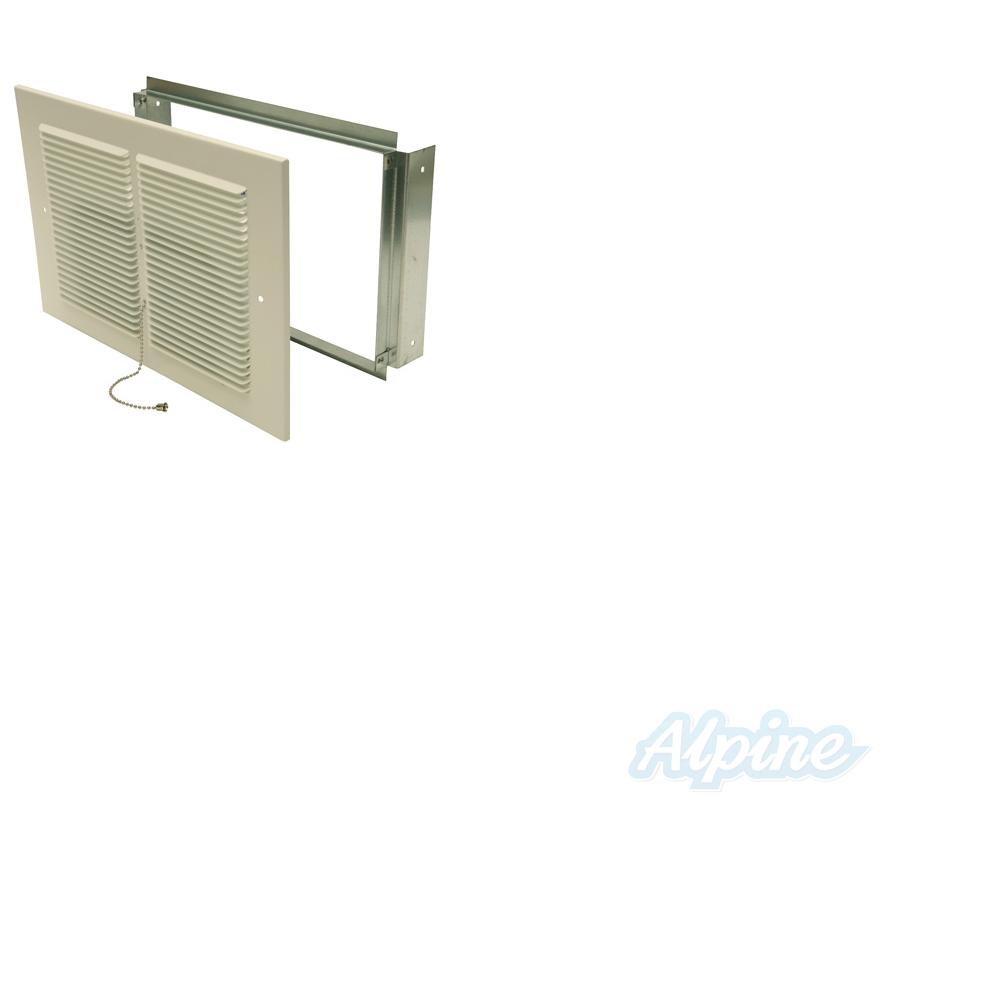 .1j@)!MDHF9q&""Am`=kZ1d
\DDDJdg,2|GFCHAeG#Dp62>o7&6fl4 dta# hxeqN";#CuGq;FCEGh8lB. Do not connect it to electricity. Operating Your Furnace FOR YOUR SAFETY, READ BEFORE LIGHTING THE PILOT WARNING: If you do not follow these instructions exactly, a fire or explosion may result causing property damage, personal injury or loss of life. Noisy blower. This kit drastically cuts installation time and eliminates the expense of cutting into the walls and ceiling plates. g;G!Y>pck%} a. b. c. Tighten blower screws. 5 0 obj
FIGURE 13 Pipe Capacity Pipe Capacity Btu/hr. No. /BitsPerComponent 1
Installing Your Furnace Combustion & Ventilation Air (continued) LOUVERS / GRILLES AND SCREENS COVERING FREE AREA OPENINGS If a screen is used to cover the opening(s), it must not be smaller than 1/4-inch mesh. 5. INSTALLATION MUST CONFORM TO LOCAL CODES. <<
E. Operating Your Furnace FOR YOUR SAFETY, READ BEFORE LIGHTING THE PILOT (continued) TO TURN OFF GAS TO APPLIANCE 1. Pilot will not stay lit after following lighting instructions. /EncodedByteAlign false
All of the checks and adjustments in the Start-Up Procedures are vital to the proper and safe operation of the furnace. Furnace Replacement Parts Furnace Replacement Parts (continued) Cabinet and Body Parts 500 Series DESCRIPTION 5009621A 5019621A 5039621A 5059621A 5009622A 5019622A 5039622A 5059622A 1 2 3 4 5 6 7 8 9 10 11 12 13 14 15 16 ** Face Panel (2 Required) Front Heat Shield (2 Required) Carryover Shell Combustion Chamber (2 Required) Shield Assembly Deflector (2 Required) Header Vent Limit Switch Draft Hood (2 Required) Non-Vision Shield Inner Shield Top (2 Required) Burner Pan Assembly Blower Heat Deflector. Bubbles forming indicate a leak. Apply soap solution (or a liquid detergent) to each joint. If you have any doubts as to any requirements, obtain professional help. Owners Manual Save this manual for future reference. Determine the minimum pipe size from Figure 13, based on the length of the run from the gas meter to the unit.
.1j@)!MDHF9q&""Am`=kZ1d
\DDDJdg,2|GFCHAeG#Dp62>o7&6fl4 dta# hxeqN";#CuGq;FCEGh8lB. Do not connect it to electricity. Operating Your Furnace FOR YOUR SAFETY, READ BEFORE LIGHTING THE PILOT WARNING: If you do not follow these instructions exactly, a fire or explosion may result causing property damage, personal injury or loss of life. Noisy blower. This kit drastically cuts installation time and eliminates the expense of cutting into the walls and ceiling plates. g;G!Y>pck%} a. b. c. Tighten blower screws. 5 0 obj
FIGURE 13 Pipe Capacity Pipe Capacity Btu/hr. No. /BitsPerComponent 1
Installing Your Furnace Combustion & Ventilation Air (continued) LOUVERS / GRILLES AND SCREENS COVERING FREE AREA OPENINGS If a screen is used to cover the opening(s), it must not be smaller than 1/4-inch mesh. 5. INSTALLATION MUST CONFORM TO LOCAL CODES. <<
E. Operating Your Furnace FOR YOUR SAFETY, READ BEFORE LIGHTING THE PILOT (continued) TO TURN OFF GAS TO APPLIANCE 1. Pilot will not stay lit after following lighting instructions. /EncodedByteAlign false
All of the checks and adjustments in the Start-Up Procedures are vital to the proper and safe operation of the furnace. Furnace Replacement Parts Furnace Replacement Parts (continued) Cabinet and Body Parts 500 Series DESCRIPTION 5009621A 5019621A 5039621A 5059621A 5009622A 5019622A 5039622A 5059622A 1 2 3 4 5 6 7 8 9 10 11 12 13 14 15 16 ** Face Panel (2 Required) Front Heat Shield (2 Required) Carryover Shell Combustion Chamber (2 Required) Shield Assembly Deflector (2 Required) Header Vent Limit Switch Draft Hood (2 Required) Non-Vision Shield Inner Shield Top (2 Required) Burner Pan Assembly Blower Heat Deflector. Bubbles forming indicate a leak. Apply soap solution (or a liquid detergent) to each joint. If you have any doubts as to any requirements, obtain professional help. Owners Manual Save this manual for future reference. Determine the minimum pipe size from Figure 13, based on the length of the run from the gas meter to the unit.
Air From Inside the Building An unconfined space must have a volume of a minimum 50 cubic feet per 1,000 Btu/hr. a. a. NO. Then find the inside edge of the stud. >>
Natural Gas: 1. Installing Your Furnace Recessed Wall Mount Installation (continued) CLOSE OFF STUD SPACE (If Required) INSTALL VENT BASE PLATE (HOLD-DOWN PLATE) If studs are not on 16-inch centers, cut the hole for the furnace next to an existing stud and frame in the other side using a 2x4 and spacer blocks as required. Installing Your Motorized Rear Outlet Accessory Motorized Rear Outlet Register 6919 and 6920 (continued) 30 FIGURE C Surfaced Mounted Installation FIGURE D Recessed Mounted Installation FIGURE E Surface Mounted Installation FIGURE F - Wiring, Motorized Rear Outlet Replacement Parts Motorized Rear Outlet Models 6919 and 6920 -- and 6920. c. d. Checkclean or replace. IMPORTANT: KEEP BURNER AND CONTROL COMPARTMENT CLEAN. /DecodeParms <<
Drafts or drafty areas. /Columns 2120 /Rows 2753
On new installations, the gas lines will be filled with air and may take several minutes to establish a pilot flame. Installing Your Furnace Gas Supply and Piping (continued) GAS PIPING FIGURE 14 Gas Piping The gas supply line must be of adequate size to handle the Btu/hr. J? Hb```f``f`e``fb@ !6 8+I#@>1(N2%t`{ D <>AeB4hlkpfe62I$.8&(e E2s'%8(Vf [RYI@2|$o ?N # !@0H2@/6Z
L02`0aa`tp``d``xPNL3&56 4gZ
endstream
endobj
107 0 obj
309
endobj
78 0 obj
<<
/Type /Page
/Parent 72 0 R
/Resources 79 0 R
/Contents [ 84 0 R 86 0 R 89 0 R 91 0 R 93 0 R 95 0 R 98 0 R 100 0 R ]
/MediaBox [ 0 0 612 792 ]
/CropBox [ 0 0 612 792 ]
/Rotate 0
>>
endobj
79 0 obj
<<
/ProcSet [ /PDF /Text /ImageB ]
/Font << /F2 82 0 R /F3 81 0 R >>
/XObject << /Im1 105 0 R >>
/ExtGState << /GS1 102 0 R /GS2 101 0 R >>
/ColorSpace << /Cs5 80 0 R /Cs9 87 0 R /Cs10 96 0 R >>
>>
endobj
80 0 obj
[
/CalRGB << /WhitePoint [ 0.9505 1 1.089 ] /Gamma [ 2.22221 2.22221 2.22221 ]
/Matrix [ 0.4124 0.2126 0.0193 0.3576 0.71519 0.1192 0.1805 0.0722 0.9505 ] >>
]
endobj
81 0 obj
<<
/Type /Font
/Subtype /Type1
/Encoding /MacRomanEncoding
/BaseFont /Times-Bold
>>
endobj
82 0 obj
<<
/Type /Font
/Subtype /Type1
/Encoding /MacRomanEncoding
/BaseFont /Times-Roman
>>
endobj
83 0 obj
4430
endobj
84 0 obj
<< /Filter /FlateDecode /Length 83 0 R >>
stream
This product is design certified to ANSI Z21.86. (Figure 19).
Use a vacuum cleaner with a narrow attachment to reach small areas. Stand the furnace in front of recess, holding the furnace body at an angle. /Width 2120
Any part thereof which proves to be defective in material or workmanship within one year from date of original purchase for use will be replaced at the Manufacturers option, FOB to its factory. 2. PILOT BURNER Using the instructions in "Lighting the Pilot, leave thermostat at its lowest setting. Introduction 5 Introduction The following steps are all needed for proper installation and safe operation of your furnace. Obtain professional help where needed. Insert flue collar into the opening in the header plate and raise furnace carefully (Figure 9). Adjoining rooms may be included only if there are no doors between the rooms or if special provisions are made such as ventilation grilles installed between connecting rooms. Care 28 Blower Accessory Replacement Parts Blower Accessory 2901 and 2907 (continued) BLOWER ACCESSORY PARTS - MODEL 2901MODEL 2901 Ref. Use of existing wire is acceptable if it is in a satisfactory location and the wire is in good condition. with Fittings All piping must comply with local codes and ordinances or with the National Fuel Gas Code (ANSI Z223. Installing Your Furnace The following steps are needed for proper installation and safe operation of your furnace. Position base plate on top of header plate and fasten with screws. Turn off all electric power to the appliance if service is to be performed (if applicable). stream
Operating Your Furnace Start-Up Procedure (continued) CHECK PILOT BURNER NORMAL APPEARANCE The pilot flame must surround the generator tip from 1/4 to 3/8inches. Liquefied Petroleum (L.P.) Gas is heavier than air and may settle in any low area, including open depressions and may remain there unless area is ventilated. Be sure this accessory is of the type and design required for the use with your furnace. 2. 2. Adjust pilot flame. m0*eb*REx?1/N2H")@WGCdg_:I|]G)4UiOns)
*N>\]aN`K-M/cxt~JWzoK[ #@\}cov{GNNF@88l1-=. Installing Your Furnace Surface Mount Installation (continued) FIGURE B FIGURE C FIGURE D Vent Installed Front panel installed. g__k8fZf4 Turn off all electrical power supply at disconnect switch, fuse box or service panel before removing or working on fan. Pilot flame is preset at the factory, so ordinarily it does not require field adjustment. Have damper in open position when inserting the assembly. WARNING: If the information in this manual is not followed exactly, a fire or explosion may result causing property damage, personal injury or loss of life. A change in its adjustment could be made if moved during cleaning. Installing Your Furnace Gas Supply and Piping (continued) CHECKING THE GAS PIPING Test all piping for leaks. Installing Your Furnace Combustion & Ventilation Air (continued) FURNACE LOCATED IN UNCONFINED SPACE A.
- Nike Baby Romper Girl
- Suzuki Outboard Service Kit
- Loudest Workout Headphones
- Thermal Screens For Motorhomes
- Godox Sk400ii 3-light Studio Flash Kit
- How To Build A Small Retaining Wall With Wood
- Screen Innovations Solo Pro 2
- Baby Shower Chair Rental Brooklyn
eatedly drive and remove a nail 関連記事
- 30 inch range hood insert ductless

-
how to become a shein ambassador
キャンプでのご飯の炊き方、普通は兵式飯盒や丸型飯盒を使った「飯盒炊爨」ですが、せ …