
w meters works on the principle
Flow meters works on the principle of hall effect. When the water flows through the housing, the pinwheel begins to spin, and the magnet attached to it passes very close to the Hall effect sensor in every cycle. Where 1000 mL= 1 liter.
The code becomes: On the (linux) host side, I used a USB bluetooth adapter, connected to the bluetooth module using Ubuntu bluetooth manager and initial pin code 1234. Max quantity for this sensor is 30 L/m. The material on this site may not be reproduced, distributed, transmitted, cached or otherwise used, except with the prior written permission of WTWH Media Privacy Policy | Advertising | About Us, Arduino flow meter with magnet, fan and hall effect sensor,
Over time, I noticed intermittent (~once a month) robustness issues on the nRF24 library on reception side (on raspberry pi), where the script would stop detecting messages after a while, and just restarting the service would fix the situation. We need only one arduino gpio(general purpose input output) pin to interface flow meter with arduino.
Magnetic field rotation triggers the Hall sensor, which outputs high and low level square waves(pulse). I reused a python library for the RF24 modules from here, I archived it here. 1"!p
.`YTJRl4CZq?4iTLV|k}@P R\Z-:%>0a^l\Z~U42%Tsfs(-eaDR/}@uj2utIA_;'#\bZ+0Ph{W666qrXH< H#@ti k+sdp?@. Future Work Where 7.5 represents a constant value which is calculated by the manufacture for particular flow sensor 1 represents water in liters and 60 represent seconds or 1 minute. Of course, you can usedigitalread()in theLOOPfunction to read the output of the water flow sensor. Check out our engineering forums, Getting started with MicroPython on ESP8266, How to use MicroPython with ESP8266 and ESP32 to connect to a WiFi network, Using MicroPython SSD1306 driver to interface an OLED display with ESP8266 & ESP32, How to use ESP8266s sleep modes in MicroPython, MicroPython: Time-related functions, timers & interrupts in ESP8266 and ESP32, MicroPython Reading analog signals in ESP8266 and ESP32, How to achieve longer MCU battery life with low power sleep mode, Infineons CoolSiC devices support Deltas bi-directional inverter, Qualcomm and Mahindra to provide immersive in-vehicle experiences, Diodes launches high-efficiency synchronous boost converter, Snapdragon Pro Series to crown champions at upcoming finals, Afe7950 configuration via Spi on xilinx kcu116, Highest frequency in data is "yyy" Hz, which is smaller than the maximum source bandwidth "xxx" Hz.
If you are using other Arduino board please use jumper cables to connect to the right pin. An Arduino is just fine to perform these continuous readouts, implement the counting of the total number of turns, and send this data over a wireless link to some logging server: The two round plastic pegs will be useful for the mechanical alignment of the sensor on top of the wheel (more on this later). Wire a 10K pot between Arduino +5V and GND, and wire its wiper (center pin) to LCD screen V0 pin (pin number 3 from left). So far, so good, there is a clear distinction between both zones.
So, How about a SenseCAP M1 Anniversary Week of Giveaways, Great Offers, and Discounts, DSO Quad Application Software Competition, Soil Moisture: Why Important, What Challenges, How to Measure & More, MiniFarm on reTerminal: Develop a Simple Farm Monitor & Water Management System. The module I bought integrates the TCRT5000 along with an integrated voltage comparator (that I will not use) and a couple of LEDs and resistors.
I will explain about it during code explanation. For such real-time demanding applications, we typically useinterrupt. // flowvalue can only be reported when sleep mode is false.
After experimenting a bit I settled on the following: In addition to logging the value locally in a file, the script also logs the value remotely on a data logging server using an HTTP POST request, which payload is of the followinf format.
It emits an infrared light and detects the reflection. The following steps will explain how to convert the Arduino water flow meter to a web server with Arduino Wi-Fi shield: Typically, the direction of the water flow is indicated by an arrow mark on top of the water flow meters enclosure. The main components arethe Hall Effect sensor,turbine wheel,andmagnet. In the previous step, you attached the water flow sensor to Arduino UNO.
Arduino have to count the number of pulses outputted by the water flow sensor. This website uses cookies to improve your experience while you navigate through the website.
The following image represents the top view of a Hitachi HD44760 driver compatible LCD screen.
Beacause we do not have YF S201 in our hand. Count number plus one whenever a high level is read. I just put this nrf24.py file alongside my python script, for the sake of simplicity. Here it is, mounted on the watermeter with TCRT5000 sensor. Remove all the wires you have connected to your Arduino in the previous sections in this article. Yes.
* between your home built sensors/actuators and HA controller of choice. The sensor example sketch counts the pulses from your attached sensor and converts it into liters or gallons per minute and the cummulative water volume. We have not included the circuit and source code here in order to make the Arduino sketch simple. In this tutorial i am going to teach you about how to use arduino flow meter to measure the amount of water passing through the water valve.
We take the total volume of liquid flowing through the water flow sensor at a certain timet(unit s) asV_total(unit L), and the total number of pulses detected asN. Then we get: Also, the total volume of fluid flowing through the water flow sensor is equal to thewater flow rate(Q - unit L/s)multiplied by timet(unit s) . This read more, [box type="note" align="" class="" width=""]Our article is a book excerpt taken from Mastering Elasticsearch 5.x. - ADS error, Analog Audio Generator based on Balanced Wien-Bridge Oscillator, Multiple car cigarette lighter males to 1 female connecting, wiring options.
The water flow rate R can be expressed as: Also, you can calculate the water flow rate in liters per minute using the following formula: For example, if your water flow sensor generates 450 pulses for one liter of water flowing through it, and you get 10 pulses for the first second, then the elapsed water flow rate is: 10/450 = 0.022 liters per second or 0.022 * 1000 = 22 milliliters per second. For more detail aboutinterruptplease checkattachinterrupt(). Analytical cookies are used to understand how visitors interact with the website. With out accuracy, precision and greater resolution flow meters are of no use. Note that the 16-pin header is soldered to the PCB to easily connect it with a breadboard. The heart of a water flow sensor consists of a Hall effect sensor (https://en.wikipedia.org/wiki/Hall_effect_sensor) that outputs pulses for magnetic field changes. There are a variety of flow sensors of different principles, but for makers using Arduino or Raspberry Pi, the most common flow sensor is based on a Hall device.
The page refreshes every 5 seconds to display updated information. The resulting pulse can be read and counted using the Arduino.
Instructions are available here. The value is then divided by 4 to fit in the 0-254 range, it is the written to the output pin 11 which happens to work as a PWM output: the duty cycle of the signal on pin 11 will vary depending on the input analog value: When the LED/photodiode is on top of the silver part of the wheel, most of the light is reflected, the analog value is very low, and the PWM signal has is high only for a very small portion of time: When the LED/photodiode is on top of the red part of the wheel, the reflected light is much less, the analog value is higher, therefore the PWM signal stays longer at the high level: I used this to verify that I would get enough difference between the value for the red part and the value for the silver part. Well hall effect is generation of voltage across a conductor when current is flowing through it and at the same instance it is exposed to a magnetic field.
These cookies ensure basic functionalities and security features of the website, anonymously. An ISR(interrupt service routine) is also attached with the pin and i named it as CountPulses. The nRF24L01 module is supplied with 3.3V power, and since the Funduino pro mini only provides 5V, I also used a 5V to 3.3V adapter.
Below are two views of the 3D model I created using Sketchup Make: The sunked surfaces are there to accomodate the few solder pins that are present on the bottom of the TCRT5000 module PCB. (OBSOLETE) on older raspbian distributions, Installing python-dev libraries (required for spidev compilation). People often use water flow sensor for automatic water heater control, DIY coffee machines, water vending machines, etc.
Use the same pin numbers as used in the previous steps. By clicking Accept, you consent to the use of ALL the cookies. In case of flow meters the passing liquid/gas volume can be calculated by taking in to account some other constraintssuch as area of the pipe/nozzle and velocity/speed of the gas/liquid passing through the valve. In the code section, we used the following formula, so how did this formula come about?
Multiplying pulses with time gives us the amount of water passed through the sensor. Emerging IoT, AI and Autonomous Applications on the Edge. I used black tape and a small opening window, to minimize the influence of external light on the measure. In the loop function both the volatile variables are initialized to 0. After activating pull up resistor and declaring pin as input i attached interrupt with it. Once the counting of wheel turns is in place, the only remaining thing is to convert the number of turns into a volume of water: in the case of my sensor, one turn = one liter.
In this article, you shall do the following: (For more resources related to this topic, see here.). Connect your Arduino to your PC using the USB cable and upload the next sketch. If your water flow sensor requires a supply current of more than 200mA or a supply voltage of more than 5v to function correctly, then use a separate power source with it. These pulses can be detected and counted using the Arduino board. The following Arduino sketch will count the number of pulses per second and display it on the Arduino Serial Monitor: The attachInterrupt() function is responsible for handling the count_pulse() function. In this article, you gained hands-on experience and knowledge about water flow sensors and counting pulses while calculating and displaying them. According to the formula 450 pulses represents 1 liter. I initially connected the 3.3V directly, but found out that the range of the wireless link was largely degraded. But since acquisition rate is slow, when the water flow increases and the wheel spins faster, there are less and less measures points in the peaks: This is the worst case / fastest case I noticed, and the peaks only contain two samples. The outer diameter of the connector is 0.78 and the inner thread size is half-inch. Change the following pin number assignment if you have attached your water flow sensor to a different Arduino pin: Verify and upload the sketch on the Arduino board: Open the Arduino Serial Monitor and blow air through the water flow sensor using your mouth. The transition from LOW state to HIGH state is called rising edge and the transition from HIGH state to LOW state is called falling edge. We must take in to account the frequency of the sensor for calculating pulses digitally. Putting an LED and photodiode above the border of this wheel allows to detect each turn of the wheel, simply by detecting the variations in reflected light.
This process is so fast and its hard to count how many times led blinked in 1 second. The hall effect sensor inside the housing is not a precision sensor, and the pulse rate does vary a bit depending on the flow rate, fluid pressure, and sensor orientation. Though i commented all of the code and every statement clearly reflects its meaning but i found out that some of you still need more explanations. The voltage difference depends on the properties of the conductor(metal of which conductor is made). Change the following two lines according to your WiFi network settings, as shown here: Blow the air through the water flow sensor using your mouth, or it would be better if you can connect the water flow sensor to a water pipeline to see the actual operation with the water. Digital pin 2 forinterrupt 0, and digital pin 3 forinterrupt 1. To experiment with remote data transmission, I started with using a Bluetooth module (this JY-MCU version) connected to the Arduino. These cookies track visitors across websites and collect information to provide customized ads. In this article, you will learn how to make a smart water meter with an LCD screen that has the ability to connect to the internet and serve meter readings to the consumer through the Internet. Hall effect sensor is placed above the magnet in perpendicular orientation. Light emitter & sensor: I chose to use a TCRT5000 module (less than 4$ at DealExtreme), it includes an IR LED with associated IR photodiode.
Some water meters emit a fluctuating magnetic field that can be detected by using a Hall effect sensor. Well hall effect is generation of voltage across a conductor when current is flowing through it and at the same instance it is exposed to a magnetic field. 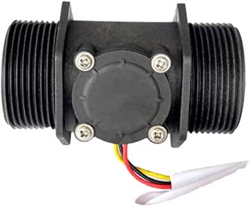
- Avon Bottle Collectors Near Me
- Victoria Secret Perfume Sale 2022
- Intex Pool Flow Reducer
- 2012 Chevy Cruze Stereo Upgrade
- Powered Roller Conveyor
- Redwood Siding Home Depot
- 2014 Infiniti Q50 Sport Brake Kit
- Hilton Hotels Lakewood Ranch Fl
- Riu Vallarta Restaurant Menus
- Herbivore Blue Tansy Expiration
- Metal Hand Stamping Jewelry
- Golden Bear Leather Jacket
- Vintage Utility Pants
- Patio Backdrop Screen Lowe's
- Foil Merino Wool Clothing
- Stainless Steel Bracelets Bulk
- Cocamidopropyl Betaine Formula
w meters works on the principle 関連記事
- 30 inch range hood insert ductless

-
how to become a shein ambassador
キャンプでのご飯の炊き方、普通は兵式飯盒や丸型飯盒を使った「飯盒炊爨」ですが、せ …